One L of a change in thinking
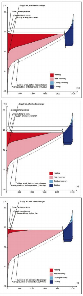
The proportion of a building’s annual heating load that can be met by heat recovery (pink area in these graphs) depends on the method of heat recovery. From the left are a run-around coil, plate heat exchanger and non-hygroscopic thermal wheel. In all cases, only a small part of the cooling requirement can be met by energy recovery.
• Targeting improved efficiencies and performances in energy-using devices such as chillers and fans.
• Promoting the use of energy-recovery devices. Better building design There are many issues with regard to building design that will be affected by the changes in Part L. For example, the air tightness of buildings will increase, reducing the leakage allowance from 12 m3/h/m2 at 50 Pa to 10 m3/h/m2 at 50 Pa. These lower rates will reduce the energy lost through leaks, impacting on the ventilation required to maintain an acceptable air quality and also the amount of energy required to ventilate. Efforts have to be made to reduce solar gains, both by use of materials and glazing with better thermal transmittance properties and also by external shading. We may see a reduction in the glass towers that have grown up around us over the last 20 years. Mechanical air handling is one of the largest energy users in air-conditioned offices, often outstripping energy use in chillers. Air handling in offices typically uses 42 to 44 kWh/m2/a whereas best-practice installations can achieve roughly half that. Many systems are simply over designed; loads greater than 120 W/m2 are excessive and with best practice should be around 80 W/m2. Improved efficiencies In addition the Building Regulations set a maximum specific fan power (SFP) for ventilation. The SFP is the total power consumption of all fans in a system in watts divided by the volume flow of the system in litres/second. For central systems providing heating and cooling without energy recovery, SFP targets are 2 W/l/s in new buildings and 2.5 W/l/s in refurbishments. In buildings with energy recovery, the SFP targets are 2.5 W/l/s in new buildings and 3.0 W/litre/sec in refurbishments. Hospitals and schools can comply by following NHS and DfEE guidelines, respectively. Mechanical ventilation systems should be capable of achieving an SFP at 25% of its design duty flow rate which is no greater than that achieved at 100%. This should be achievable with most speed-control systems, especially EC drives and variable-frequency drives. There are fixed losses in motors and drives that would remain the same at lower speeds. Some motors become less efficient at reduced speeds. However this is offset by the power fan law — impeller shaft power varies as the cube of the speed, so at a quarter of the full speed the fan shaft power will be 1/64th of the full-speed fan power, or less than 2%. Motors should be EFF1 type high-efficiency motors. There are more stringent targets on cooling equipment such as chillers and condensing units The heating, cooling and ventilation systems should be provided with zone, timing and demand controls. However, some designers feel that they are meeting their obligations as long as there is some form of energy recovery in the air-handling system, irrespective of efficiency. This is not the case, for the reduction in energy used in a building is dramatically affected by the efficiency of the energy-recovery component. Energy-saving devices There are several methods of energy recovery (traditionally called heat recovery). Devices used in air-handling units for air-to-air energy recovery are thermal wheels, plate heat exchangers and run-around coil systems. Each system has its pros and cons, and each has its own applications. Thermal wheels are the most efficient method of energy recovery. These will recover up to 90% (typically 75 to 85%) of the energy in the extract air. Another major benefit is that they are only 500 mm in length irrespective of size required. Plate heat exchangers are generally regarded as the next most efficient method of energy recovery. These will recover between 50 to 65% of the energy in the extract air. They transfer sensible heat only and due to the efficiencies are not often used for cooling recovery. Run-around coils are probably the most common form of heat recovery. This is predominantly because they have no risk of transfer between extract and supply airflows and hence are ideal for hospitals. Efficiencies are generally 45 to 55%, although most are designed for around 50% energy recovery. These systems are highly flexible as the extract coil can be in a different plant room if necessary. Flakt Woods has developed the run-around coil system that is up to 75% efficient (i.e. 50% more efficient than a standard run-around coil). The system is called Econet and has large coils to maximise the amount of energy recovered from the extract air. These large coils achieve energy-recovery efficiencies of 65 to 75%. The more efficient the energy-recovery device, the less energy needs to be generated for heating and cooling, so that less energy is used in achieving the conditions required. The three graphs show the temperature duration curves for a Ecoterm run-around-coil system designed at 42% efficiency, a Recuterm plate heat exchanger at 57% efficiency, and a Regoterm thermal wheel at 76% efficiency. You will note from the graphs that the heating requirement (red area) reduces as the efficiency increases. You will also notice that the amount of time the heating needs to be on is reduced as the efficiency increases. The efficiencies stated ‘undersell’ the devices. For example, a thermal wheel with an efficiency of 76% reduces the annual heat demand by around 95%. The 76% is derived from the energy recovered at peak load. At any other moment the amount recovered increases until, at a certain condition, the energy-recovery device supplies all heating required. (in this instance, the heating system needs to be on for 1100 h a year as opposed to 2300 h for the run-around coil with an efficiency of 42%). These calculations are based on Flakt Woods Acon Software for AHUs with an electricity cost of 6p/kWh. Summary As you can see, the new regulations will lead to fairly radical changes in design, materials and components — all for the better. However, we should avoid paying lip service by just putting in some improvements. We should constantly be optimising the overall building system by using the most efficient of every component part of the building. Craig McFadyen is system projects manager with Fläkt Woods.